The types of waveguides shown above are hollow in the center and made up of copper walls. 3 pts Using the results of steps 9 and 10 establish the procedure for finding the cutoff frequencies of all TE and TM modes in a circular waveguide.

Te And Tm Mode Patterns In A Metallic Circular Waveguide Youtube
Numerical methods such as the beam propagation method are typically used for analyzing such waveguides eg.
. Acces PDF Circular Waveguide Tutorial of how to determine unloadedContains a compendium of the most frequently used data in day-to-day telecommunications engineering work. Cutoff Frequency equation for circular waveguide fc is defined below fc 18412 c 2pia Where c is the speed of light within waveguide and a is the radius of the circular cross section. Fc For dominant mode TE11.
Dominant mode in rectangular waveguide is TE10 and in circular waveguide is TE11. Tables graphs figures formulae nomograms performance curves standards highlights constants and statistics. These days I am unfolding before you 12 uncomplicated 3D nail artwork designs ideas trends stickers.
Identify those that are singular at the origin and explain why they should be discarded. You can find the number of modes that can be propagated with the lowest attenuation in any typ. Circular Waveguide Tutorial For dominant mode TE10 m1 n0 and hence λ c 2broad dimension 2a Circular waveguide.
Fc For dominant mode TE11 λ c 171diameter171d Waveguide Propagation modes. Designed for easy and rapid access. As previously the waveguide in 30 cm long and its radius is 10 cm.
Cutoff Frequency equation for circular waveguide fc is defined below fc 18412 c 2pia Where c is the speed of light within waveguide and a is the radius of the circular cross section. 25 we can perform the same sequence of steps in cylindrical coordinates as we did in rectangular coordinates to find the transverse field components in terms of the longitudinal ie. If the analysis involves some lossy part such as a nonzero conductivity or an open boundary the eigenvalue is complex.
Optical Waveguide Modes covers single- and few. Design a Circular dielectric waveguide with a high permittivity central core of radius a11483m and relative permittivityεr 20 surrounded by air cladding. Circular Waveguide Modes Tutorial.
The cutoff frequency for the considered mode is 1148 GHz thus the waveguide is excited at 2 GHz which is above the cutoff frequency. 24 Circular Waveguide x y a Figure 25. So run the simulation time domain it takes some minutes after that right click on port 1 in ports section at navigation tree at the left side of your screen and select object information and set frequency to 13 GHz then calculate the modes.
Figure depicts Circular waveguide. Acces PDF Circular Waveguide Tutorial A complete guide to optical waveguide modes This in-depth work explains how transverse optical waveguide geometry influences field distribution and polarization properties. Simulating the Waveguide Before editing any of the default parameters you need to select your excitation frequency A good frequency to look at is the cutoff frequency of your Waveguide For the cutoff frequency can be calculated using the equation below.
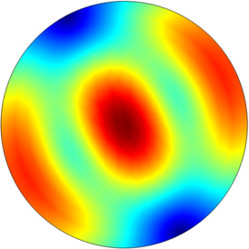
Let us now compare the transmission lines and waveguides. Various TE and TM modes are supported in waveguide. In this part of the tutorial the fields distribution for the TM 01 mode in a circular waveguide is presented.
In the window of defining waveguide port change mode number to 3 in order to find 3 initial modes of circular waveguide. It looks as shown in fig3. In such situations the real and imaginary parts have separate interpretations.
Project 6 HFSS Circular Dielectric Waveguide Design Requirements. A waveguide mode is a transverse field pattern whose amplitude and polarization profiles remain constant along the longitudinal z coordinate. Waveguide modes exist that are characteristic of a particular waveguide structure.
Get Free Circular Waveguide Tutorial The Analysis of the Effect of an Obstacle on the Electromagnetic Field in a Circular Cylindrical Wave Guide Physics of Waves A complete guide to optical waveguide modes This in-depth work explains how transverse optical waveguide geometry influences field distribution and polarization properties. You will gain a. Mode TE 11 In this part the distribution of transverse and longitudinal fields components of TE.
Calculate the cut off frequency of the 6 modes and plot the propagation constant vs. These have a thin lining of Au or Ag on the inner surface. Speed of light within waveguide and a is the radius of the circular cross section.
The waveguide mode in circular waveguide is described with m and n indexes which stand for the field variation in radial and axial directions respectively. Introduce the notation TE m n and TM m n where m is the integer number from step 8 and n is. 2 days agoCutoff Frequency equation for circular waveguide fc is defined below fc 18412 c 2pia Where c is the.
You will gain a thorough understanding of the fundamental physics of mode structure. Cutoff Frequency equation for circular waveguide fc is defined below fc 18412 c 2pia Where c is the speed of light within waveguide and a is the radius of the circular cross section. 2 1 2002 75 The simplified equation above comes from the.
Notes on the Rectangular Waveguide Most classic waveguide example Some of the first waveguides used for microwaves Not a transmission line because it has only one conductor Does not support a TEM mode. For a circular waveguide of radius a Fig. Silicon-on-insulator waveguides modes TE and TM mode electric field distributions.
In case of circular waveguides the fundamental mode is TE 11. This quantity is often but not always real valued. The following figures show the types of waveguides.
Modes are recognised in case of circular waveguides. Rectangular waveguides are analyzed a bit like each axis were its own parallel plate waveguide. In mode analysis it is usually the primary goal to find a propagation constant.
Circular waveguide modes tutorial New and latest patterns are increasingly being launched by professionals so Increasingly more ladies can Keep to the streak of nail art. In this video we will learn how to perform the mode analysis. Circular optical fibers non-planar dielectric waveguides generally do not have analytical solutions for their guided mode characteristics.
Therefore the electric and magnetic fields of a mode can be written in the following form. A circular waveguide of radius a.

Circular Waveguide Modes Associated To The Cases Of One Symmetry Download Table
2

Field Pattern Of The Tm01 Mode In A Circular Waveguide Download Scientific Diagram

4 7 Circular Waveguide Rf And Microwave Engineering Fundamentals Of Wireless Communications Book

Circular Waveguide Modes Associated To The Cases Of One Symmetry Download Table
Lossy Circular Waveguide

Waveguide Modes
2
0 comments
Post a Comment